Hall Effect Sensor Tester
5 min read
Wednesday 14 October 2026
Being the member of the Nitro Junkie team that (mostly) knows how to work a computer, it often falls to me to figure out the on-board RacePak data logger. Not being the most experienced with such things, I often find myself in a position where I'm wondering if the actual sensor is at fault, or if it's some configuration problem in the logger itself. This becomes a problem since it's hard to test all these sensors with the bike taken apart, but it's difficult to physically access some of them with it completely together. To attempt to solve at least some of this, I wanted to put together a simple tester for the hall effect sensors used to measure various RPM signals.
Hall effect sensors
A hall effect sensor is quite simple. It's purpose is to indicate when a magnet is close by. These can either be digital or analogue. An analogue sensor is a little more complicated as the effect varies with distance between the sensor and magnet, so you need a comparator set up correctly to give a clean HIGH/LOW signal. Luckily as far as I can tell the RacePak only supports digital sensors which already output a more standard HIGH/LOW. Our sensors are a mixture we've inherited from various places so I'm not certain of the specification, but from testing they seem to run on anything above about 5v, and will put out 3v when HIGH and 0v when LOW. The sensor I have for testing is HIGH by default and drops LOW when a magnet is detected.
In an application like ours, we want to measure speed of a rotating shaft. To achieve this, a magnet (or several magnets) is embedded in the shaft. The data logger can then be told how many magnets it's looking for, and count the signals to calculate an RPM signal. The trouble with this, is that the alignment of the sensors is critical. Too close to the magnet and you hit it, not a good outcome when things are spinning at a few thousand RPM. But too far and you'll get no signal. To add to this, it's not possible to turn most of these things by hand fast enough to get a signal on the RacePak. The tool I'm designing aims to assist in checking the sensor actually works, and that it's aligned with it's magnet.
The idea
The basic idea was a device that would connect to one of the sensors while it was in situ on the bike, and give some kind of indication when a magnet is detected. No speed required, and tells you that everything before the logger (except the wiring run) is working. I'm told I'm not the first to this idea and that some of the fancier brands have built in LEDs for that purpose.
Designing
I'm not an expert at analogue electronics, and that's selling it a bit highly. I know the basics but I'm mostly a computer guy so I generally gravitate towards microcontrollers and code. While that 100% would have been viable for this. It felt a bit overkill, and doing some passive electronics seemed like an interesting challenge.
I knew I needed to battery power this, as we're often troubleshooting this at the race track, so I started by experimenting with a sensor I brought back from Nitro Junkie HQ. Research seemed to suggest that the RacePak drives it's sensors at 12v (though I haven't measured this). I initially tried a 3v input, and while that did drive the signal wire HIGH, I got no reaction from a magnet. I probably should have expected that. A bit of research told me that that is a fairly standard failure mode for a hall sensor that's running on too low a voltage. Bumping it up to 5v did seem to fix things, I got 3v with no magnet, dropping immediately to 0v with one. This is also where I learned that polarity matters, these sensors react to north or south, not both. At the risk of frying the sensor (since I have no documentation for it) I tried 12v just to check it behaved the same. It did, so 5v or so input it is. High enough to be a little annoying, but more achievable in a reasonable form factor than 12v. I went with 4 AAA batteries. They're a but bulky but easy to find while at the track.
Not knowing the rating of any of the sensors, I didn't want to drive any LEDs directly off the signal line from the sensor, so I wired up a simple transistor to switch an LED:
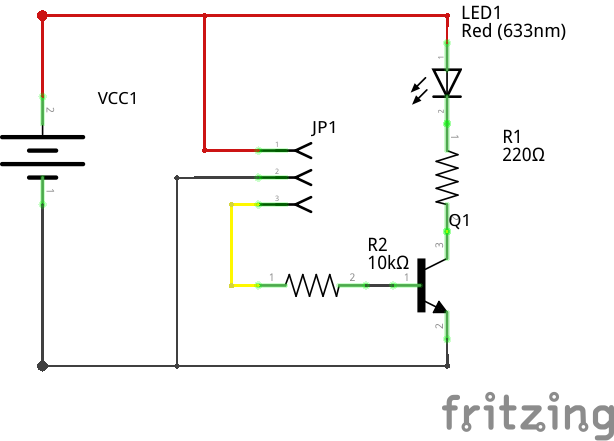
Easy enough, although I obviously decided I needed a bit more of a challenge. I wanted an LED that would be on all the time, except when a magnet was present. In hindsight, this only really serves to test the batteries, and an always on LED would have been fine. But I did enjoy the exercise. With a lot of research, some experimentation, and some assistance from our new AI overlords, I settled on this circuit:
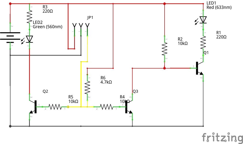
This requires a digital sensor, and pulls the input HIGH, so any sensor will need to pull the pin LOW to change the LEDs. It won't work with analogue sensors.
Building
Having settled on a circuit, I started building. Initially on a breadboard powered by my bench PSU to prove out the circuit, then onto a perf-board. This does make it painfully obvious that it's homemade, but serves the purpose for a one-off. At some point I may use this as an excuse to get some custom PCBs made, but for now this is functional.
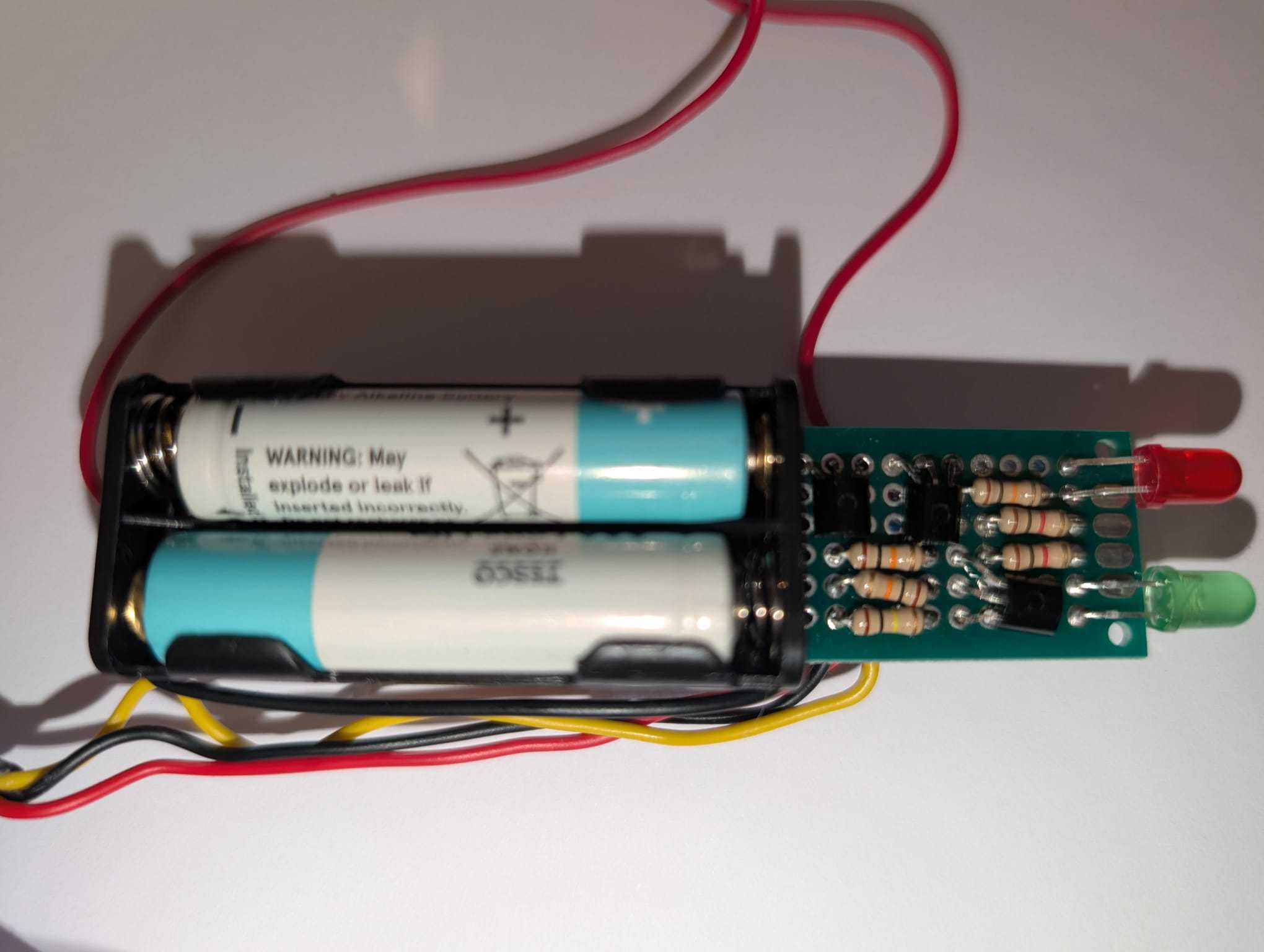
For connection to the sensor, I added about a foot of 3 core flex terminated in the Molex connector we use all over the place for the data logger. I plugged in the sensor and checked it worked.
As a final touch I designed a very quick (read as a bit ugly) case to house everything in.
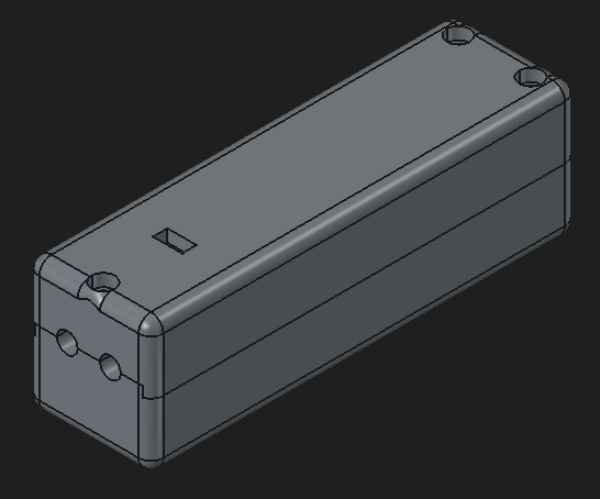
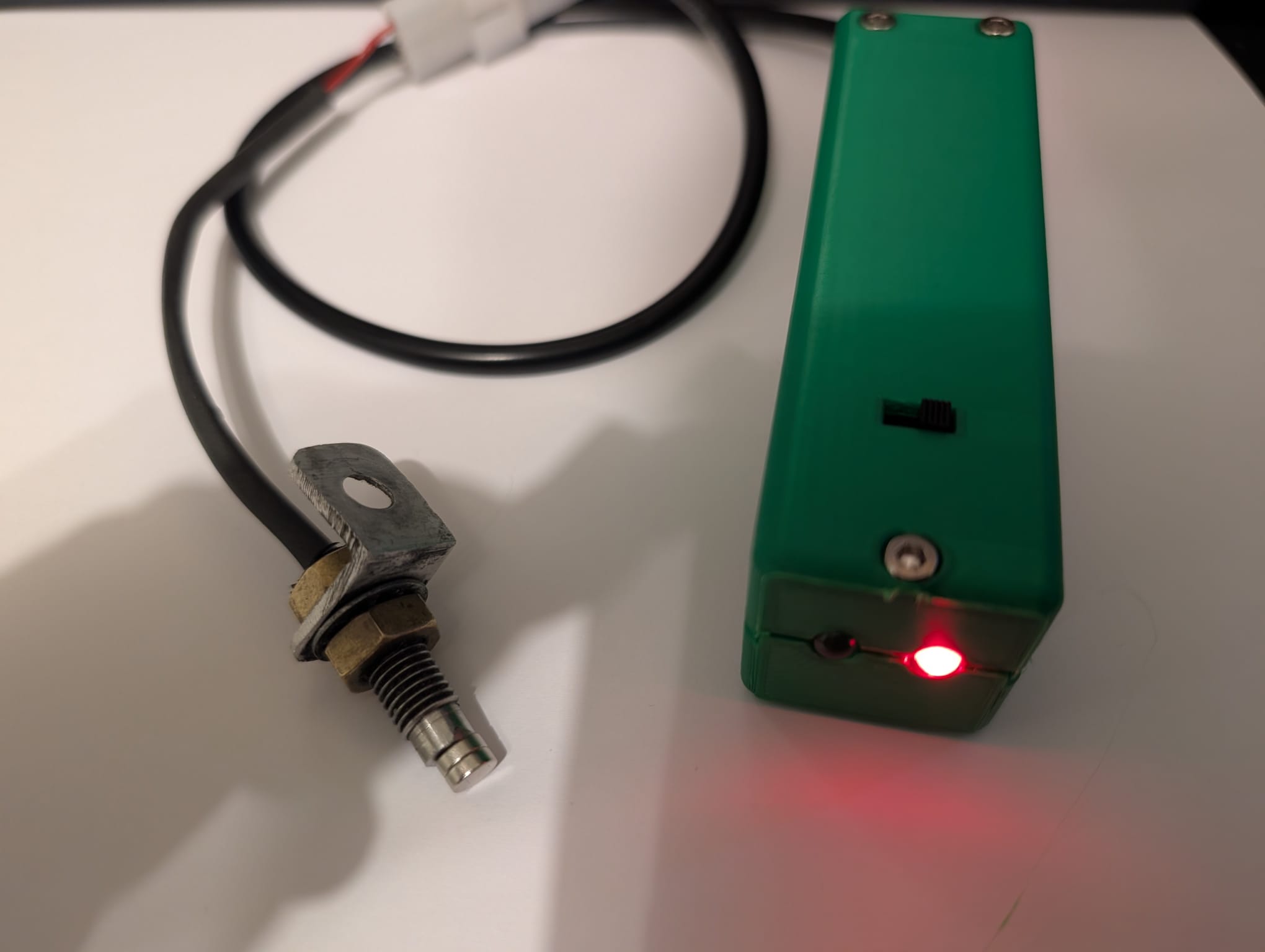
On the one sensor I took home to test, this tool does exactly what I needed. I'll report back once we've used it a few times on the bike.